Overview
This document outlines proper procedures for moving or transporting the Standup 2.0 short distances (final mile), like from your warehouse to your end customer, or from one customer location to another.
Final mile transport is is not the same as repacking for RMA/return shipments to Bevi. For that topic, refer to: Repacking the Standup 2.0 for RMA/Return Shipping.
Going the Final Mile
The shipping process can subject any item to rigorous vibrations. Whether you are moving a machine from one customer to another, transporting The Standup 2.0 horizontally, or moving it to or from to your warehouse, you need to check the machine to ensure it is ready to operate for its next Installation.
NOTE: For any machine that was installed at any point, be sure to drain all lines and the Ice Bank before moving the unit to the customer, IT IS CRITICAL THAT YOU FOLLOW THE STANDUP 2.0 DECOMMISSIONING GUIDE. Any water left in the Bevi machine will cause damage and issues in transit, as well as become unsanitary.
- To re-enter the Installation mode after a machine is decommissioned, plug it back into power and its water source. Enter the Service Panel on the touchscreen and select “Installation Mode” from the “Troubleshooting Tools” section.
Key Points and Takeaways
The Standup 2.0 can be shipped on its back if ALL the following are TRUE:
- Transport on its back is for the “LAST MILE” delivery only. The Standup 2.0 must not be transported horizontally over long distances.
- No objects are placed on top of the machine during horizontal transport.
- Unit must be moved on its back only when horizontal; DO NOT lay the unit on its sides or front as cracks, dents, and damage to internal components could occur.
- Ensure unit is NOT MARKED with an “Only Ship Upright” label (shown below), which signifies an early production of The Standup 2.0. Please check the rear panel of the machine for the label.
- 👉 NOTE: It is CRITICAL that the unit stands upright for a minimum of 4 hours before turning on power. The coolant in the chiller needs to settle. Not allowing for this could cause permanent damage to the chiller.
- Other Bevi Standup versions (like the 1.5) cannot be shipped horizontally at any time.

Vertical Transport (Last Mile) Guidance
(Applies to all Bevi Standup Units)
Required Tools
- Dolly (appliance dolly with straps)
- Moving blankets x 3 (or reuse the foam pieces from original packaging)
- Collapsible cart
- Ratchet straps x 2
- Ratchet strap extender
- A van with ~70” of vertical clearance
- 2 technicians for maneuvering the machine on the dolly
Loading The Machine
- In a team of two, position the appliance dolly behind the machine.
- Place a moving blanket over the unit to prevent damage.
- One person holds the dolly while the other pushes the unit onto the lower lip and then proceeds to strap the unit to the dolly.
- Deploy and use the extra set of wheels when moving the unit long distances to make it easier and safer.

NOTE: Utilize a dolly to move the machine. It is acceptable not to use a dolly only when moving the machine into its final position (less than 5 feet).

- Wheel the dolly onto the lift gate and position it vertically, retracting the extra set of wheels. One person holds the unit on the lift gate while the other raises the lift gate.

- Proceed by tipping the unit down and pulling it into the van, leaving the extra wheels retracted.
NOTE: Pay extra attention to the clearance at the doorway of the van to not damage the unit in the process.

- Pull the unit all the way in against the dividing partition. The unit can be left on the dolly during this time or taken off the dolly and secured by itself.
- Use 2 ratchet straps to secure the unit against the partition using the e-tracks provided.

Unloading Machine
- Loosen the ratchet straps. Re-secure the unit to the dolly following the previous steps. Roll the dolly with the unit out onto the lift gate and follow the same safe techniques as described above. Lower the lift gate to ground level.

- If you’re unloading onto a dock, you may find that the ramp will have to be placed at an incline to reach. At this point in a team of two, turn the dolly with the back to the loading dock and pull the unit up the ramp onto the loading dock.
- Deploy the extra set of wheels at this time to stabilize the load for the move inside the building to the desired install location.
Once in place, visually inspect the unit for any damage.
Horizontal Shipping
🛑 NOTE: NOT TO BE USED for Standup 1.5, or early Standup 2.0s with the “only ship upright” label
Required Tools
- Dolly (appliance dolly with straps)
- Moving blankets x3 (or reuse foam pieces from original packaging)
- Collapsible cart
- 2 technicians for maneuvering the machine
NOTE: If this process is being followed for a unit that has been USED, be sure it is properly drained of ALL water and ALL consumables are removed. Follow the guide for Decommissioning the Bevi Standup 2.0. To re-enter Installation mode after a machine is Decommissioned, plug it back into power and its water source, and select “Installation Mode” from the “Troubleshooting Tools” section.
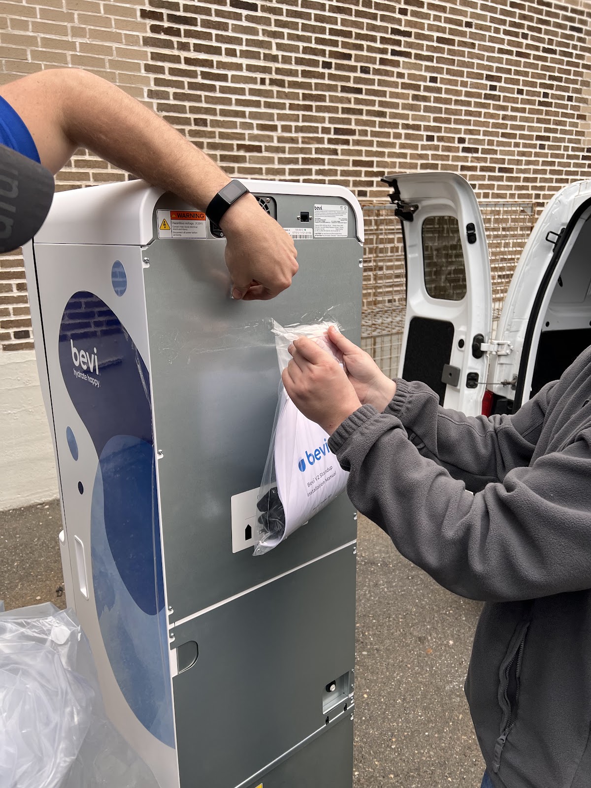
- Remove the bag covering The Standup 2.0. Don't try to load the unit with the bag on since it prevents you from having a good grip.
- Remove the manual, power cord, and power cord clip from the back of the machine and put these in a safe place as you will need them later.

- Place a moving blanket on the floor of the vehicle.
- Fold another moving blanket and place it over the bumper/door latch of the vehicle.

- Using 2 people, push the Bevi machine against the vehicle bumper, then carefully tilt the top into the vehicle, laying it on its back.
DO NOT PLACE ON ITS SIDE OR FRONT AT ANY TIME!!

- Lift up from the bottom and slide the Bevi into the van.
NOTE: Only slide the Bevi machine when resting on a soft, non-marring surface like a moving blanket.

- Take the blanket from the bumper and drape it over the machine (ensure the blanket is clean).
- Strap the machine down if possible.
Visually Check Internal Components
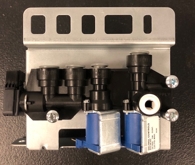
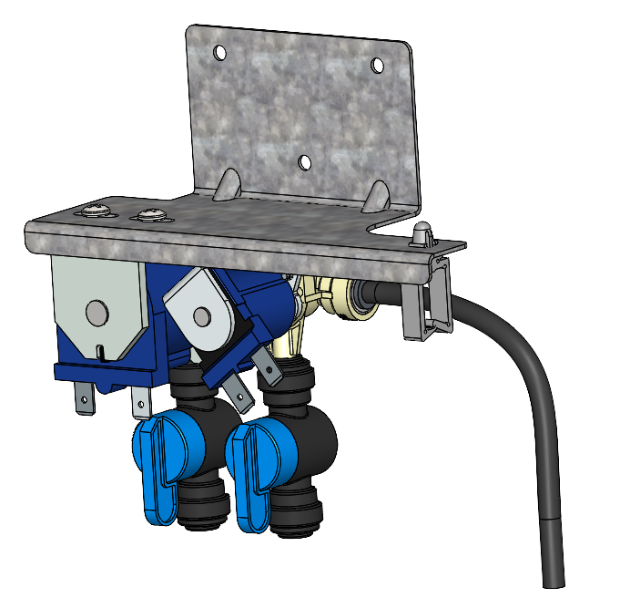
Check all plumbing connections to make sure nothing got loose during transit.
- Visually check all connections into the manifolds.
- Manifold 1, located behind the external water source inlet.
- Manifold 2, located to the right of the top of the hot water heater and is fastened to the bracket that holds the buffer tank.
- Manifold 3, located on the inside of the door, to the left of the nozzle assembly which is hidden behind the printed restocking instructions card.
- Hot water tube from heater to nozzle
- Manifold 1, located behind the external water source inlet.


Open the door and check for water in the interior basin.
- If you notice water in the base before you plug it in, this could mean that there was some residual water in the ice bank. Please remove any water in the base and check that the float sensor is free, by removing the float sensor. For instructions on how to do this, please see our document at THIS LINK.

Location of float switch on top of chiller, accessed via rear machine panel.
Visually Check Outside of Machine
- Front of the door - Inspect for scratches or dents.
- Touchscreen - Inspect for scratches or cracks
- Power Switch - Inspect for damage to the power switch.
- Back panels - Ensure there are no missing screws or visible damage.
- Casters - Inspect for damage from move