Overview
The buffer tank holds a reserve of water for the Bevi to draw from, which helps provide a consistent dispensing flow rate. In the Standup 2.0, water passes through Manifold 1 to the filter, then to the buffer tank. From the buffer tank, water then returns to Manifold 1.
Before proceeding with removal/replacement, ensure that troubleshooting or Bevi Support has confirmed a faulty buffer tank. These instructions apply to Standup 2.0 machines only.
Alert Details: Replace Buffer Tank
A machine alert to “Replace Buffer Tank” may appear when the Bevi has detected that the buffer tank is damaged and requires replacement. A damaged buffer tank can cause symptoms such as loss of flow, early dispense run out, and sparkling dispense gas outs.
When this alert appears, follow the steps below to replace the buffer tank and properly log the service to clear the alert.
In this Article (click to jump):
- Required Tools & Materials
- Removing the Buffer Tank
- Installing the new Buffer Tank
- Testing Function & Completing Service
Required Tools & Materials
- Buffer Tank with 3/8” Fittings (FRU P/N 720-0345)
- (2x) 24” replacement tie wraps (included in P/N 720-0345)
- (2x) 6" replacement zip ties (NOTE: not included in P/N 720-0345)
- Flush cutters to clip existing zip ties and trim new zip ties
- #2 Stubby Phillips Screwdriver
- Socket wrench with 6" extension
- 3/8" socket
Removing the Buffer Tank
Task 1: Access the Service Panel
- Tap the Service Icon in the upper left corner of the main dispense screen.
- Tap “Start Service”
- Enter the PIN (1986) to access the service panel. The door should automatically open.
- If on another screen, select the “Service” tab.
- Door will open automatically. You can also press the “open door” button onscreen if needed.
- From the service panel, access the Troubleshooting Tools screen.
- Tap “Alerts and Maintenance”, then tap “Troubleshooting Tools”.
Task 2: Turn off the Water Supply.
- Locate the shutoff valve on the water supply behind the Bevi.
- Close the shutoff valve by turning the blue handle 90 degrees.
Shutoff shown in closed position.
✔️ Open valve = Inline with outlet water flow/tube
🚫 Closed valve = 90 degrees/perpendicular to outlet water flow/tube
Task 3: Drain the Buffer Tank and Depressurize the Water Line.
- With the door open, ensure the Buffer Tank valve is in the open position. The valve should be pointing to the RIGHT when open.
- The Buffer Tank can be accessed through the hole just above the filter head.
- Place a bucket under the Filter Flush Valve, and open the shutoff valve by turning 90 degrees.
- Allow the Buffer Tank to drain until no water is coming from the Filter Flush Valve.
- Once the Buffer tank has been drained, close both the Filter Flush and Buffer Tank valves.
- From Troubleshooting Tools, pour COLD water to depressurize the supply line.
- Place a container under the nozzle.
- Press and hold the POUR button for cold water for 5 seconds.
| WARNING | |
|
HAZARDOUS VOLTAGE (120 V / 240 V). CONTACT MAY CAUSE ELECTRICAL SHOCK AND INJURY. DISCONNECT POWER BEFORE SERVICING. |
|
Task 4: Power off the Bevi and unplug the power cord.
- On the back of the Bevi at the top, turn off the power switch.
- Disconnect the power cord from the back of the Bevi.
Task 5: Remove the center panel from the back of the Bevi.
- Loosen the 4 screws in the corners of the panel.
- The screws do not need to be fully removed.
- Lift the panel up to unhook from the screws, and remove.
- Place the panel to the side.
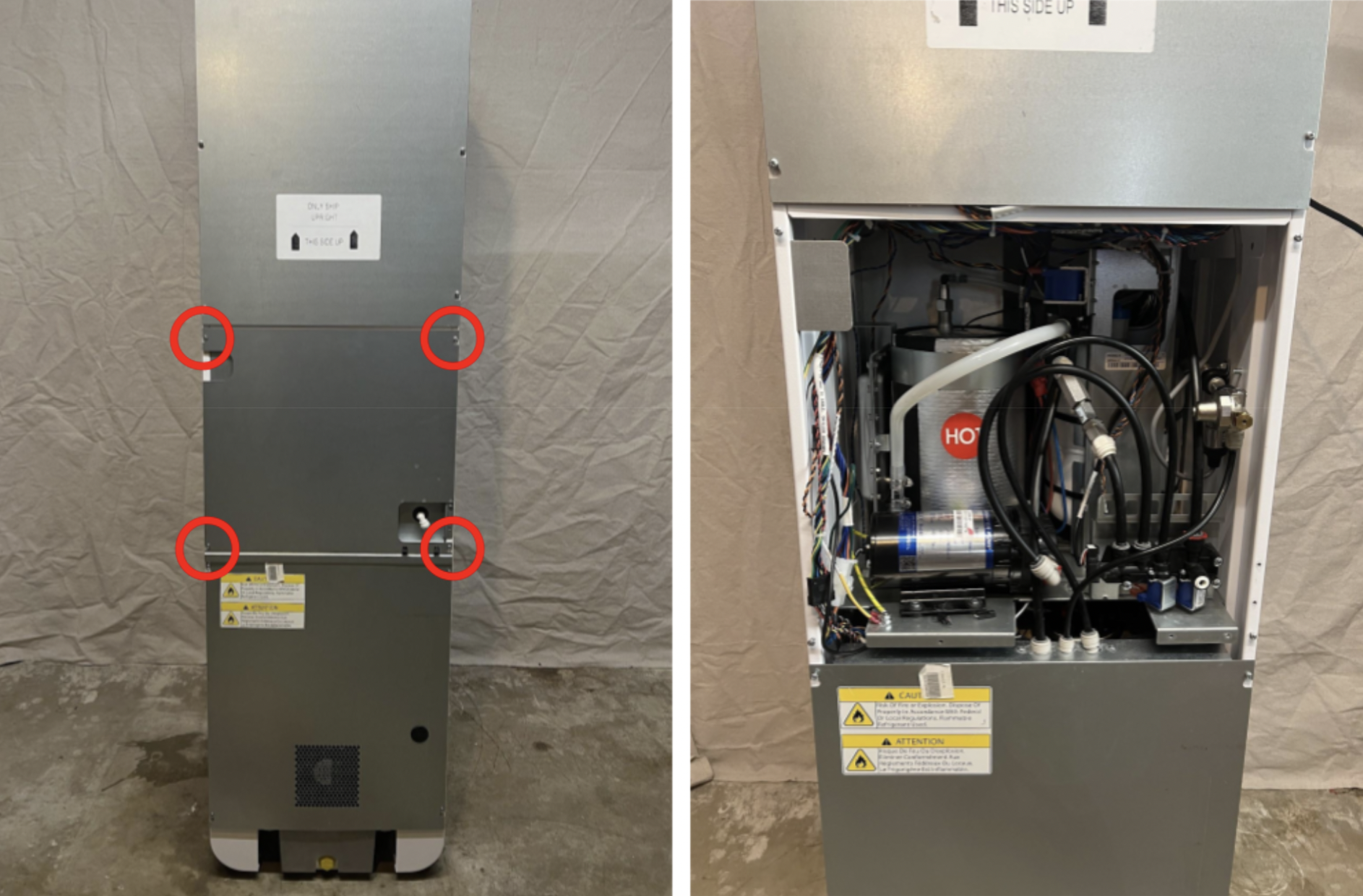 Task 6: Remove Manifold 2 from Buffer Tank bracket
- Disconnect the two wiring connections for the hot water dispense solenoid.
- Using a #2 stubby phillips screwdriver, remove the two screws that hold Manifold 2 to the bracket.
- You do not need to disconnect any tubing from Manifold 2.
- Once removed from Buffer Tank bracket, leave to the side.
- Retain screws: Place screws to the side in a safe place, as they will be needed for reinstallation.
- Remove the red locking clip and disconnect the 3/8" tubing from the top of the backflow preventer.
Task 7: Identify CO2 Regulator Version
- Depending on the installed CO2 Regulator version, you may need to move the regulator to allow space for the Buffer Tank to be removed.
- If a Gen 1 Regulator is installed, it can remain in place and continue to Task 8 (click to jump).
- If a Gen 2 Regulator is installed, it will need to be moved in order to remove the Buffer Tank, continue to the next step.
- If a Gen 2 Regulator is installed, remove the two 3/8” nylock nuts securing the regulator bracket to the machine chassis.
- Remove the bracket from the two threaded mounting studs.
- The regulator does not need to be fully removed from the Bevi.
Task 8: Removing the Buffer Tank and bracket
- Carefully, cut the zip ties securing the wiring to the buffer tank bracket.
- Remove the 3 screws that secure the bracket to the chassis.
- One single phillips screw at the top.
- Two screws at the base of bracket.
- These can also be removed with either a #3 Phillips screwdriver, or a 3/8" wrench.
- Retain screws: Place screws to the side in a safe place, as they will be needed for reinstallation.
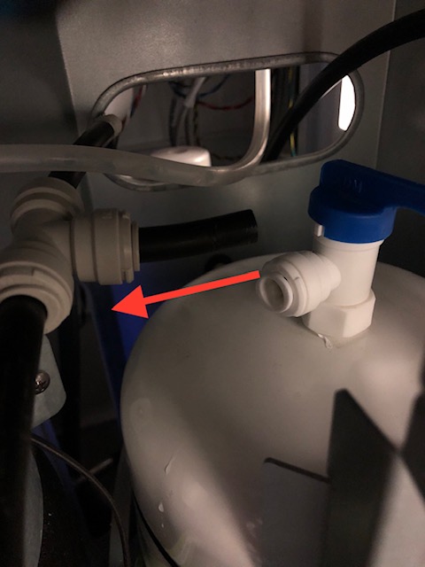
- Disconnect the Buffer Tank valve.
- Disconnect the 3/8" tubing from the Buffer Tank valve fitting.
- Do not disconnect the tubing from the T fitting.
- Disconnect the 3/8" tubing from the Buffer Tank valve fitting.
- Remove the Buffer Tank and bracket from the machine.
- Tip the top of the tank backwards, and slide out.
- If you identified a Gen 2 CO2 Regulator in Task 7, you will need to move the regulator down and out of the way to allow the Buffer Tank to slide out.
- Be careful to not kink the 1/4" CO2 tubing.
- Cut the two (2) zip ties securing the Buffer Tank to the bracket.
- Take note of how these zip ties are routed, as you will need to reinstall new ones with the replacement tank in the next steps.
Installing the New Buffer Tank
Task 9: Replace Buffer Tank
- Using new Zip Ties, secure the Buffer Tank to the Bracket.
- Replacement zip ties are supplied with the new Buffer Tank.
- Position the new Buffer Tank and bracket into the plumbing shelf.
- Lay the tank flat and slide into place bottom-first.
- Stand tank and bracket upright once in position.
- Reinstall the 3 mounting screws for the Buffer Tank Bracket.
- It is helpful to loosely install the top screw first, followed by the bottom two.
- Reconnect the water tubing to the Buffer Tank. Ensure tubing is fully seated, and replace red clips on all fittings.
- Open the buffer tank valve.
Task 10: Reinstall Manifold and CO2 Regulator
- Reinstall Manifold 2.
- Reinstall 2 phillips screws holding the manifold to the buffer tank bracket.
- It is helpful to first start the rear screw, and leave loose.
- Once both screws are installed, tighten down fully.
- Reconnect manifold 2 wiring connections.
- NOTE: Solenoid wiring connections do not have any polarity, they can be connected either way.
- Reconnect the 3/8" tubing to the backflow preventer.
- Ensure tubing is fully seated.
- Replace the red locking clip.
- Secure Manifold 1 wiring back in its original position on the buffer tank bracket with new zip ties.
- For Gen 2 CO2 Regulators, reinstall the mounting bracket onto the threaded studs, and secure with the two 3/8" nylock nuts.
Testing Function & Completing Service
Task 11: Connect Water Line
- Measure flow rate from the water source:
- Install a flow meter and pressure gauge on the inlet line.
- Place a bucket underneath the inlet line and open the shut off valve.
- Measure flow rate of water.
- Close the shut off valve and measure pressure of inlet water.
- Remove flow meter and gauge.
- Reconnect the 1/4" water source to the inlet:
- Ensure the tubing is fully seated in the push-to-connect fitting.
- Turn on the water source:
- Position the shutoff valve handle inline with the water flow.
Task 12: Functionality Test
- Plug in the power cord and power on the Bevi.
- Ensure you have turned on the water supply and opened the buffer tank valve.
- From the Service Panel, access “Troubleshooting Tools”. (See steps from Task 1)
- Under the Controls menu, open the inlet solenoid.
- This allows water flow into the machine to fill the buffer tank.
- Observe the plumbing shelf for leaks.
- If any leaks are present, recheck that all tubing connections are fully seated in fittings.
- Dispense 1-2 liters of still water to ensure there is a steady flow of water through the system.
- Dispense 1-2 liters of sparkling water to refill the carbonator.
- Test sparkling water to verify proper carbonation.
- Dispense 0.5 liters of hot water to ensure manifold 2 connections are intact.
Task 13: Reinstall back panel
- Reinstall the back panel.
- Ensure no cabling is pinched between the panel and the machine.
- Use caution while reinstalling panels, and do not make contact with the interior of machine when power is connected.
Resolving the Machine Alert
Task 14: Resolve the "Replace Buffer Tank" Alert (if present)
NOTE: If you are replacing the buffer tank for a separate reason and there is no alert present, this task may not be required.
- From the Troubleshooting Tools screen, touch “Back to Alerts”
- Touch “Troubleshoot” next to the Replace Buffer Tank alert.
- Enter the last 10 digits of the Buffer Tank serial number that was recorded from the new tank.
- Once a valid serial number is entered, touch “Mark Resolved”.