Overview
This guide is designed to troubleshoot low water flow when trying to dispense a beverage from The Standup 2.0. Depending on this issue, this document may direct you to a different Replace or Fix article for the component (FRU).
Required Tools (if applicable)
- Flashlight
- Number 2 Philips Head screwdriver (to remove the back panel if needed)
- PIN Number to open the door of the Bevi (1986)
- Voltmeter (if available)
- Empty container with liter measurement markings (bucket, large cup, etc.)
Warnings:
- The Standup 2.0 uses 120 volts of power to run, please make sure all precautions are taken to prevent electrical shock. Disconnect power before removing back panels.
- The Standup 2.0 Dispenses HOT water, please note that you should make sure all precautions are taken to avoid a burn injury.
Common Causes for Low or No Flow of Water
| Component | Reason | Recommended Fix |
| Source water valve | Closed or not fully open | Open (See Task 1) |
| Source water | Insufficient supply pressure/flow | Contact building facilities for pressure/flow issues. The Standup 2.0 requires a minimum 40 psi input water pressure. (See Task 1) |
| Filter | Full, clogged, or missing | Replace (See Task 2) |
| Dispense Ball Valves | Closed or not fully Open | Open (See Task 3) |
| Inlet Ball Valve | Closed or not fully Open | Open (See Task 1) |
| Kinked Source Line | Tube folded when machine put in place | Check for folds - Replace if a kink or fold was found (See Task 1) |
| Backflow preventer | Installed incorrectly | Reverse direction |
| Demand Pump | Not plugged in/defective | Plug in or replace (See Task 5) |
| Buffer Tank | Ball valve closed/Bladder Pierced | Open or Replace (See Task 4) |
| Manifolds 1,2, or 3 | Unplugged/defective | Check connections/Replace (See Task 6) |
| Hot water line | Kinked line | Check for folds in line - Replace if fold or kinks are found |
| Frozen Ice Bank | Coil misalignment, sensor damage, refrigerant issue | Replace Chiller and/or Base Control Board (BUCB) (See Task 7) |
Troubleshooting
Task 1: Check source water & connections.
With the water turned on to the machine, verify the following by following the troubleshooting steps below.

- Check all source water valves are fully open (as shown here). Shutoff valves may be located in the back of the machine as well as closer to the water source (which may be by a sink).
- Open the door to the machine by tapping “Explore” and then “Service”. Enter the access PIN “1986” to open the door and access the main screen of the Service Panel.


WARNING: Please be aware that The Standup 2.0 has a hot water system that can burn skin. Please use caution when working on and troubleshooting plumbing issues.
Task 2: Check the Filter & Inlet Valve.
In the Service Panel, a red filter cartridge, or a red circle with a “1” next to the filter button, indicates that the filter needs to be replaced (as shown below). Check the last time the filter was changed as an old filter can cause restricted water flow. If appropriate, use the Filter Swap Wizard to change the filter and test the water to ensure normal flow has returned.
If the filter is not at the end of its usable life, check the health of the filter and the function of the inlet valve:

- Close the Buffer Tank: Turn the blue valve handle clockwise until it stops (blue handle should be perpendicular to the tube exiting the top of the buffer tank).
-
Check that the inlet valve operates correctly and the filter is in good condition:
- Navigate to the Machine Alerts > Troubleshooting Tools section of the service panel.
- In the Controls section, select “OPEN” for “Inlet solenoid”.
- Position an empty container under the Filter Flush Valve. Open the Filter Flush Valve to measure the flow of water through the inlet valve and filter.
- If no water comes out, the inlet valve may not be functioning. Check the cabling to Manifold 1 and swap the Manifold, cable and/or Base Unit Control Board (BUCB) if necessary.
- If water is flowing less than 1.5 LPM (fills less than 1.5 liters in 1 minute), the filter should be replaced. Use the Filter Swap Wizard to replace.
- If water is flowing normally (1.5 LPM or more), CLOSE the Filter Flush Valve, OPEN the Buffer Tank Valve, and continue to Task 3.
Task 3: Check the still & sparkling shutoff valves.
There are two ball valves located on the door inside in the front of the machine that will not allow water to dispense if left closed.
- Remove the inner door instruction panel by gently prying up the 3 plastic tabs with either a flathead screwdriver or small needle-nose pliers. Locate the water ball valves on the inside of the front door, (they are connected to manifold 3)

- Check to see if the two ball valves below Manifold 3 are in the “ON” position by visually observing that the knob is in line with the water flow. If not, move the ball valve to the “On” position. (see below)

Task 4: Check the Buffer Tank.
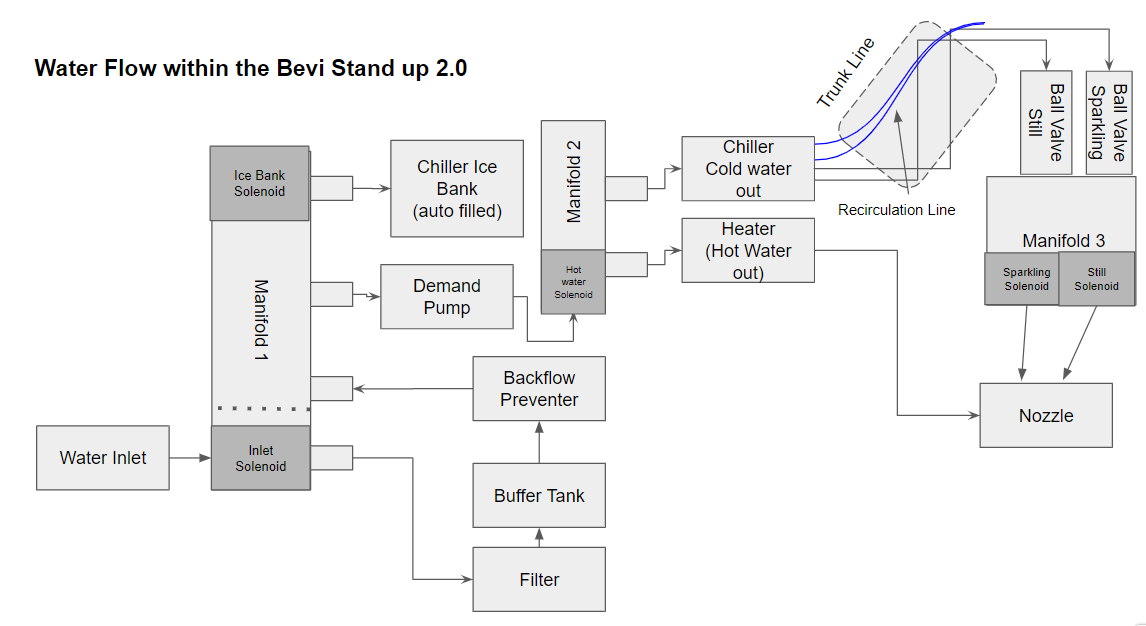
Water flows directly from the inlet valve in Manifold 1 to the filter, then to the Buffer Tank. If the Buffer tank is working properly, the following should be true:
- Buffer tank ball valve is open: The blue valve handle should be inline with the tube exiting the top of the buffer tank (fully rotated counterclockwise as shown below).


-
Buffer tank is functioning correctly: To test the function of the buffer tank, perform the following steps:
- In the service panel, navigate to “Machine Alerts” > “Troubleshooting Tools” section.
- Ensure that no dispenses have occurred for at least 5 minutes (you may need to time this manually)
- In “Troubleshooting Tools”, check that the “Inlet solenoid” is “Closed”, and “Internal water pressure” is greater than or equal to 40 psi.
- In the service panel, navigate to “Machine Alerts” > “Troubleshooting Tools” section.

- Position an empty container under the Filter Flush Valve. Open the Filter Flush Valve to measure the volume of water that exits the buffer tank through this valve.
- Water volume results:
- If greater than 1.5 L, the buffer tank is functioning properly. Dispense a small amount of Still water to allow the buffer tank to refill, then continue with troubleshooting.
- If less than 1.5 L, the buffer tank has failed and needs to be replaced. Remove the tank by following the steps located in the Remove and Replace - Buffer Tank document located on the partners.bevi.co website.
Task 5: Check the demand pump.
The demand pump provides sufficient pressure for dispenses from The Standup 2.0. Check to see that the demand pump is turning on when demand for water is initiated.

Demand Pump - Found by removing the mid back panel, on the plumbing shelf
- In the Service Panel, go to “Troubleshooting Tools”, press “POUR” to dispense “Cold Water” and listen for the demand pump to turn on. This may be difficult in noisy spaces as the pump is quiet. The body of the demand pump can be touched to feel vibrations during operation during a dispense (to access the demand pump, loosen the 4 screws in the corner of the middle back panel and lift to remove). IF the demand pump does not turn on check that there is power to the pump.

- Inspect the cable exiting the demand pump. Trace the cable to its other end at the Base Unit Control Board (BUCB) checking for any visible issues with the cable. Ensure the connector is fully seated.
- If you have a multi meter, check that there is 24V coming into the pump by unplugging the Demand pump at the BUCB board (see below) and placing your probes on the two power pins. To get voltage to the pump, enter “Troubleshooting Tools” and turn on the “Demand Pump” by selecting “ON”. The demand pump will stay on until you turn it off.
- If 24V is not present, replace the BUCB board (FRU # 720-0102).

- If there is power to the pump via the BUCB, and it is not turning on - replace the demand pump (FRU 720-0056). Find the Remove and Replace - Demand Pump document located on partners.bevi.co
Task 6: Troubleshooting Manifold 3

Manifold 3 takes chilled still and sparkling water from the chiller then outputs it to the nozzle assembly. Manifold 3 is located on the insideof the front door and is positioned on top of the ball valves discussed above.
Dispense a sparkling glass of water, and then a still glass of water. If either fails, continue in this section to troubleshoot Manifold 3.
NOTE: If one solenoid is malfunctioning, Manifold 3 must be replaced in its entirety.

- Check to see that the cables going to the solenoids of Manifold 3 are plugged in securely.
- Place an empty container under the nozzle and dispense “Cold” water. Using a multimeter, check the DC voltage between the two tabs of the larger valve.
- Dispense “Sparkling” water. Using a multimeter, check the DC voltage between the two tabs of the smaller valve.
- If the voltage measurements in both steps 2 & 3 above read 24 VDC, replace Manifold 3 (FRU 720-0064).
If there is not 24VDC when activated:
- Unplug the right-most connector on the Door Control Board labeled “Valves” (4-pin, 2 x 2). (see below)
- With a multimeter, probe the 2 lower connections on the board-side connector (furthest from the printed word “Valves”). These should read 24 VDC when dispensing COLD.
- Probe the 2 upper connections (closest to the printed word “Valves”). These should read 24 VDC when dispensing SPARKLING.
- If either of these measurements do not read 24 VDC when actuating the respective valves, replace the Door Control Board (FRU 720-0112). If both read 24 VDC, replace the cable (PN 105982-01).

Task 7 - Check for a Frozen Chiller
The chiller produces a controlled amount of ice to create cold and sparkling water. If the sensors controlling the chiller are malfunctioning, or if critical parts in the chiller are out of alignment, it is possible to grow ice over the drinking coil, preventing cold and sparkling water from dispensing.
- Check if Hot water dispenses from the system. Successfully dispensing hot water with normal flow (greater than 1.8 lpm) means water is successfully entering the machine and flowing through the filter, backflow preventer, demand pump, and heater. If hot water does not dispense normally, the issue is not related to the chiller.
- If hot water dispenses normally but cold and sparkling water streams are low / not present, the chiller may be frozen. Visually inspect the chiller for excessive ice:
NOTE: The following steps provide an overview of the chiller removal process. A more detailed instruction on chiller removal with photos can be found here.
- Turn off the inlet water from the source.
- Turn off Buffer Tank by accessing the Buffer Tank shut off valve through the access hole above the filter and turning it toward you.
- Dispense both still and sparkling water until the water stops flowing (for sparkling water you will hear CO2 coming out with no water).
- Turn off the CO2 tank valve.
- Dispense Sparkling water until CO2 stops coming out
- Turn power off to the machine using the switch on the upper back of The Standup 2.0.
- Remove the 4 connections from the carbonator to the Trunk Line located in the front of the machine by taking off the retaining clips and then removing the lines (leave the elbow fittings attached to the trunk line, not the chiller)

NOTE: (Place retaining clips in a safe place as you will need them when you reconnect the trunk line)
- Remove the 2 phillips head screws on the inner panel holding the chiller in.
- Remove the lower back panel of the Bevi by using a Number 2 screwdriver.
- Unscrew the 2 hex-head phillips screws connecting the base of the chiller to the base of the machine.
- Remove the 3 inlet lines to the carbonator.
- Remove the chiller halfway to allow you to peer into the coil and icebank.


NOTE: You MAY need to disconnect the 3 electrical connections to the chiller to pull it out far enough to see in.
WARNING: The chiller is heavy, especially when filled with water. Use proper lifting techniques when moving the chiller from The Standup 2.0

- Take a flashlight and peer into the top of the chiller to view water. If all you see is ice, then the ice bank is frozen. Even if you see water, there still may be enough ice present to freeze the drinking coil. Inspect the interior of the stainless steel drinking coil for signs of ice between the coils; if ice appears between any of the coils at any point, the drinking coil is likely frozen enough to limit and/or block the flow of water.
- In the example photo above, ice has grown over a portion of the stainless steel coil, freezing the system (chiller cover removed for photo clarity).
- If you are not sure if there is ice between the drinking coils, use a transfer pump to pump out the ice bank water (this will make the ice walls more visible if they are protruding through the drinking coils).
- If the chiller is frozen, turn the power off, remove the chiller and replace.